- English
- French
- German
- Portuguese
- Spanish
- Russian
- Japanese
- Korean
- Arabic
- Greek
- German
- Turkish
- Italian
- Danish
- Romanian
- Indonesian
- Czech
- Afrikaans
- Swedish
- Polish
- Basque
- Catalan
- Esperanto
- Hindi
- Lao
- Albanian
- Amharic
- Armenian
- Azerbaijani
- Belarusian
- Bengali
- Bosnian
- Bulgarian
- Cebuano
- Chichewa
- Corsican
- Croatian
- Dutch
- Estonian
- Filipino
- Finnish
- Frisian
- Galician
- Georgian
- Gujarati
- Haitian
- Hausa
- Hawaiian
- Hebrew
- Hmong
- Hungarian
- Icelandic
- Igbo
- Javanese
- Kannada
- Kazakh
- Khmer
- Kurdish
- Kyrgyz
- Latin
- Latvian
- Lithuanian
- Luxembou..
- Macedonian
- Malagasy
- Malay
- Malayalam
- Maltese
- Maori
- Marathi
- Mongolian
- Burmese
- Nepali
- Norwegian
- Pashto
- Persian
- Punjabi
- Serbian
- Sesotho
- Sinhala
- Slovak
- Slovenian
- Somali
- Samoan
- Scots Gaelic
- Shona
- Sindhi
- Sundanese
- Swahili
- Tajik
- Tamil
- Telugu
- Thai
- Ukrainian
- Urdu
- Uzbek
- Vietnamese
- Welsh
- Xhosa
- Yiddish
- Yoruba
- Zulu
Mechanical Parts Bearing Seat: GD&T Optimization to Avoid Over-Specification and Reduce Cost
For teams sourcing Mechanical Parts Bearing Seat for automation, robotics, gearboxes and motor assemblies, over-specifying tolerances remains one of the quietest, most expensive pitfalls. These bearing seats are simple in concept but foundational to performance: they stabilize rotating shafts, damp vibration and extend the working life of bearings. Too often, though, engineers carry over tight tolerances across every feature of the part out of caution, without separating features that directly impact bearing function from those that do not. The result is longer cycle times, heavier inspection workloads and higher scrap rates, all for tolerances that deliver no real-world performance gain. Intentional GD&T practice changes this. It locks precision only where it matters, balances part performance against landed cost, and keeps procurement budgets from bleeding unnecessarily.

What is a Mechanical Parts Bearing Seat and Why is GD&T Critical?
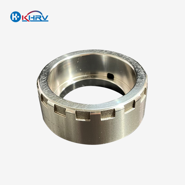
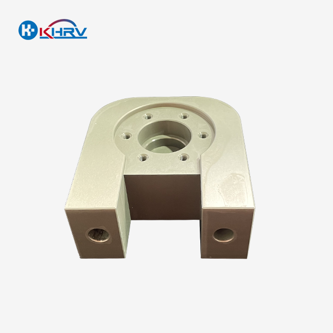
A mechanical parts bearing seat, or bearing housing, is a precision-machined component built to locate and support rolling bearings, preserve shaft alignment and control vibration under load. Its reliability does not depend on tightening every dimension across the whole part. Just a handful of geometric controls define how it will perform in service.
Bore cylindricity sits at the top of the list. It governs roundness, straightness and taper inside the bearing bore. For press-fit and transition-fit assemblies, uncontrolled cylindricity distorts the bearing race, creates uneven load distribution and leads to premature bearing failure. Perpendicularity between the bore axis and mounting datum prevents shaft tilt after assembly, cutting down noise and vibration at higher operating speeds. Total runout tracks combined radial deviation and is especially relevant for high-speed rotary setups. Position tolerance for bolt holes ensures clean alignment during assembly without forcing tight limits that add unnecessary machining difficulty. Flatness only belongs on sealing or mounting datums; side walls and clearance steps rarely require it.
This functional approach stands apart from copying blanket tight tolerances out of aerospace drawings. Purpose-built GD&T removes ambiguous dimensioning, supports interchangeability across batches, and eliminates machining and inspection work that adds no value. Tight controls on non-mating surfaces will not make the assembly run better—they only push up cost and stretch lead times.
Key characteristics that distinguish a properly toleranced bearing seat include:
- Bore cylindricity: Controls raceway distortion for press-fit and transition-fit applications.
- Perpendicularity and total runout: Maintains shaft alignment and reduces high-speed vibration.
- Position tolerance for bolt holes: Ensures fastener alignment without over-tight values that add machining difficulty.
- Flatness only where needed: Required on sealing or mounting datums; side walls and clearance steps rarely need it.
Key Applications and Advantages of GD&T-Optimized Mechanical Parts Bearing Seat in Automation
When teams tie GD&T to tiered precision rules, the savings and quality gains become tangible, especially for automation and gearbox builds.
1. Gearbox Bearing Seat—Cast Steel Housing with Optimized Bore Tolerance One gearbox manufacturer sourced cast steel bearing seats for a medium-load industrial drive.Their original drawing called for0.005mm cylindricity across all bore surfaces, regardless of fit requirements.This level of cylindricity is achieved through external cylindrical grinding after CNC machining — a process we coordinate with qualified grinding partners.Our team at Wuxi Kaihan broke down the design by function: the bearing interface retained strict cylindricity and perpendicularity, while non-mating outer profiles and clearance steps were relaxed to standard industrial tolerances. We machined these housings on 4-axis CNC equipment, holding critical bore dimensions and ±0.01 mm hole position for bolt holes. Tiered precision kept strict controls on bearing surfaces and mounting datums, while easing requirements everywhere else. The 200-piece batch shipped in 16 working days. The customer recorded a 30% drop in per-unit cost, with no measurable change to bearing lifespan or vibration behavior.
2. High-Speed Motor Seat—Aluminum 6061 with Runout Control A motor builder needed 6061 aluminum bearing seats for a high-speed servo application. Total runout and perpendicularity were non-negotiable for smooth rotation. We ran these parts on 3-axis CNC machines, holding bore cylindricity and total runout to the tiered specification, while outer geometry followed general industrial tolerances. Pre-production sample approval wrapped up in 5 working days, and the full 300-unit batch shipped in 15 days. Compared with their prior supplier, which held every surface to tight limits, the customer saw consistent high-speed performance and a 35% cost reduction.
These two projects illustrate a repeatable pattern:
- Tiered precision concentrates strict GD&T only on bearing interfaces and mounting datums; non-critical features follow standard industrial tolerances.
- Optimized GD&T typically delivers 25–40% total cost savings versus suppliers that machine every feature to overly tight tolerances.
- Lead times hold steady at 10–20 working days, with sample validation and full GD&T measurement data available for review.
Best Practices for Implementing Mechanical Parts Bearing Seat in Your Supply Chain
For engineering and procurement teams, successful GD&T optimization rests on functional decomposition and clear, aligned communication with your machining partner.
Start by breaking the part into functional zones and locking in your datum scheme. Separate the bearing interface (strict GD&T), mounting datum (moderate controls) and outer/clearance features (general drawing tolerances). Bring in a DFM review before releasing drawings for quoting. This catches over-specified tolerances, poorly chosen datums and inspection-unfriendly GD&T callouts early, before you invest in prototype machining. This tiered strategy is the simplest way to stop overpaying for precision you do not need.
Use tolerance stack-up analysis to back up every tolerance relaxation. It proves that your chosen limits keep the bearing assembly within acceptable operating boundaries, giving engineers objective evidence to justify loosening non-critical controls. If parts will be plated, anodized or nitrided, build coating stock into your CAD model and adjust inspection baselines after surface treatment, so coating thickness does not eat into your tolerance budget.
Match your material and fit class to real operating conditions. Cast steel works well for gearbox and large housings thanks to its stable machining behavior and good strength-to-weight balance. Carbon and alloy steel deliver rigidity for heavy-load work; grades like 45#(AISI 1045 equivalent) and 40Cr (AISI 5140 equivalent)can hold tight cylindricity after heat treatment, though residual stress must be relieved before finish boring. Aluminum alloys suit lightweight, high-speed automation builds. 6061 and 7075-T6 machine quickly, but lower stiffness makes ultra-tight geometric controls harder to maintain under clamping force. Stainless steel is reserved for food, medical and corrosive environments; its tendency to work-harden means tight GD&T should only be specified when corrosion resistance is mandatory.
Before locking in a supplier, verify their ability to deliver measured GD&T data. A qualified shop should have calibrated bore gauges, micrometers, height gauges and runout test fixtures on hand, demonstrate familiarity with ASME Y14.5 or ISO 1101, and provide FAI reports with measured dimensional data. For complex GD&T verification, confirm whether the supplier coordinates third-party CMM inspection when needed.Always validate samples for fit and geometric compliance before moving to full production.
Conclusion
Working with GD&T for Mechanical Parts Bearing Seat is not about finding ways to cut corners. It is about assigning precision intentionally, only where the function of the bearing assembly demands it. Reliable performance hinges on a small set of core controls: bore cylindricity, perpendicularity, runout and datum-locked position. Most cost waste happens when designers copy tight tolerances from high-precision reference parts onto standard industrial assemblies with far less demanding requirements.
By separating critical bearing interfaces from non-mating geometry, selecting fits aligned with load and speed conditions, and combining DFM reviews with tolerance stack-up checks, you strip out unnecessary machining and inspection work. At Wuxi Kaihan, we hold critical hole positions at ±0.01 mm and strict flatness standards, while non-critical surfaces follow standard industrial tolerances. We run these parts on 3-axis and 4-axis CNC machines, well suited for overseas mid-range industrial projects. With thoughtful GD&T support, component costs fall 25–40% while bearing rotation stays stable for automation, robotics and industrial machinery. For projects where cost and performance need to stay balanced, a properly toleranced bearing seat is a practical, sustainable choice for your procurement pipeline.
FAQ
1. What is a Mechanical Parts Bearing Seat and which GD&T controls are mandatory? A mechanical parts bearing seat is a precision-machined housing designed to locate and support rolling bearings. The mandatory GD&T controls are bore cylindricity, perpendicularity to the mounting datum, and total runout for high-speed applications. Bolt hole position ensures assembly alignment, while outer contours follow general industrial tolerances.
2. What materials work well for GD&T-optimized Mechanical Parts Bearing Seat machining? Common selections include cast steel for gearbox housings, carbon and alloy steel for heavy-load applications, aluminum alloys for lightweight high-speed automation, and stainless steel for corrosive or medical environments. Material choice directly impacts what tolerances are practical, and teams need to plan for stress relief and coating allowance accordingly.
3. How exactly does GD&T optimization lower the cost of Mechanical Parts Bearing Seat? Tiered tolerance planning removes unnecessary tight callouts, so you avoid extra finish boring runs, strict temperature-controlled machining requirements and excessive inspection sampling. Most customers see 25–40% cost savings on bearing seat components without sacrificing bearing function or service life.
4. What precision can Wuxi Kaihan deliver on Mechanical Parts Bearing Seat? We maintain critical hole positions at ±0.01 mm and strict flatness standards, with non-critical surfaces built to standard industrial tolerances. Our 3-axis and 4-axis CNC machines support mid-range industrial projects, backed by calibrated dimensional inspection and FAI reports with measured inspection data. Third-party CMM verification is available for projects requiring it.
Partner with KHRV for GD&T-Optimized Mechanical Parts Bearing Seat Solutions | KHRV
Ready to implement Mechanical Parts Bearing Seat with smarter tolerancing on your next build? Wuxi Kaihan Technology Co., Ltd. provides hands-on GD&T DFM reviews and precision CNC machining for automation, robotics and gearbox OEMs. Our ISO 9001:2015-certified workshop machines cast steel, alloy steel, aluminum and stainless steel bearing seats. We walk through your drawings to flag over-specified tolerances, propose realistic adjustments, and cross-reference fit requirements against bearing manufacturer datasheets.
We hold critical hole positions at ±0.01 mm and strict flatness standards, with non-critical surfaces to standard industrial tolerances, using 3-axis and 4-axis CNC machines. Our full OEM customization delivers 25–40% savings compared with suppliers that machine every feature to tight tolerances by default, with surface treatments (including anodizing and plating) coordinated through accredited external suppliers.Typical lead times run 10–20 working days.
Reach out to our engineering team at service@kaihancnc.com to talk through your requirements and get a competitive quote.
References
Miller, T. R., & Carter, J. B. (2023). GD&T Optimization for Bearing Housings: Functional Tolerancing vs Over-Specification. Journal of Manufacturing and Assembly Engineering, 46(6), 176–194.
Sánchez, L. M., & Wang, H. (2022). Tolerance Stack-Up Analysis for Rotating Bearing Seat Assemblies. International Journal of Precision Engineering, 17(9), 311–327.
Hughes, R. D., Patel, S. K., & Chen, L. (2023). Material Effects on Geometric Tolerance Attainability for CNC Boring Operations. Machining Science and Technology, 27(4), 542–561.
ASME Y14.5-2018, Geometric Dimensioning and Tolerancing. American Society of Mechanical Engineers.
ISO 1101:2017, Geometrical product specifications (GPS) — Geometrical tolerancing — Form, orientation, location and runout tolerances.
ISO 286-1:2010, Geometrical product specifications (GPS) — ISO code system for tolerances on linear sizes — Part 1: Basis of tolerances, deviations and fits.
Garcia, F. P., & Zhao, Y. (2022). DFM Practices for Cost Reduction in Precision Bearing Housing Machining. Industrial Procurement Review, 30(5), 98–114.
Learn about our latest products and discounts through SMS or email