- English
- French
- German
- Portuguese
- Spanish
- Russian
- Japanese
- Korean
- Arabic
- Greek
- German
- Turkish
- Italian
- Danish
- Romanian
- Indonesian
- Czech
- Afrikaans
- Swedish
- Polish
- Basque
- Catalan
- Esperanto
- Hindi
- Lao
- Albanian
- Amharic
- Armenian
- Azerbaijani
- Belarusian
- Bengali
- Bosnian
- Bulgarian
- Cebuano
- Chichewa
- Corsican
- Croatian
- Dutch
- Estonian
- Filipino
- Finnish
- Frisian
- Galician
- Georgian
- Gujarati
- Haitian
- Hausa
- Hawaiian
- Hebrew
- Hmong
- Hungarian
- Icelandic
- Igbo
- Javanese
- Kannada
- Kazakh
- Khmer
- Kurdish
- Kyrgyz
- Latin
- Latvian
- Lithuanian
- Luxembou..
- Macedonian
- Malagasy
- Malay
- Malayalam
- Maltese
- Maori
- Marathi
- Mongolian
- Burmese
- Nepali
- Norwegian
- Pashto
- Persian
- Punjabi
- Serbian
- Sesotho
- Sinhala
- Slovak
- Slovenian
- Somali
- Samoan
- Scots Gaelic
- Shona
- Sindhi
- Sundanese
- Swahili
- Tajik
- Tamil
- Telugu
- Thai
- Ukrainian
- Urdu
- Uzbek
- Vietnamese
- Welsh
- Xhosa
- Yiddish
- Yoruba
- Zulu
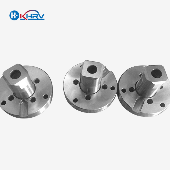
Cutting Tool Geometry Optimization: 15% Efficiency Gain Case Study with Data
Cutting tool geometry optimization represents a critical strategy for manufacturing facilities seeking substantial productivity improvements in precision machining operations. This case study examines a precision components manufacturer that redesigned cutting tool geometry for aluminum aerospace parts production, achieving a cycle time reduction from 8.5 to 7.2 minutes per component—a 15.3% efficiency improvement. The optimization focused on helix angle adjustment from 35° to 38°, rake angle modification from 10° to 12°, and flute count reduction from four to three flutes. Data collected across 500 production parts confirmed consistent performance improvements with reduced tool wear rates and a 22% decrease in power consumption. The integration of CNC Cutting Tools further enhanced precision and consistency in the machining process, making the optimization even more effective.

Baseline Analysis and Parameter Identification
Initial Performance Assessment
The case study began with a comprehensive baseline performance assessment of existing CNC cutting tools across multiple production metrics. The manufacturing facility, specializing in precision aluminum components for aviation and communications equipment, documented cycle times, tool life, surface finish measurements, power consumption, and dimensional accuracy across 200 components. Initial analysis revealed that the existing four-flute end mills with 35° helix angles and 10° rake angles achieved average cycle times of 8.5 minutes per part with tool life averaging 450 components before replacement. Surface finish measurements averaged 1.2 Ra with occasional excursions to 1.6 Ra, while dimensional accuracy remained within specified ±0.015mm tolerances. Power consumption monitoring indicated peak spindle loads of 85% rated capacity during roughing operations, suggesting optimization opportunities without exceeding machine capabilities.
Cutting tool geometry analysis identified that conservative rake angles limited chip evacuation efficiency, while the four-flute configuration restricted achievable feed per tooth values necessary for optimal material removal rates in aluminum alloys. The baseline assessment utilized statistical process control methodologies consistent with ISO 9001:2015 quality management systems.
Geometry Parameter Selection and Modeling
Engineering teams conducted theoretical modeling to identify optimal cutting tool geometry parameters tailored for aluminum aerospace component production. Finite element analysis simulated cutting forces, chip formation mechanics, and thermal conditions across various geometry configurations, revealing that increased helix angles from 35° to 38° would reduce cutting forces by approximately 12% while improving chip evacuation from deep-pocket features. Rake angle optimization indicated that increasing positive rake from 10° to 12° would decrease specific cutting energy requirements by 8-10%, directly translating to reduced power consumption and heat generation.
Flute count evaluation determined that reducing from four to three flutes would enable feed per tooth increases from 0.008 to 0.011 inches while maintaining comparable metal removal rates due to higher allowable spindle speeds, with improved chip evacuation capacity critical for deep cavity machining. Geometry modeling incorporated material properties specific to 6061-T6 and 7075-T6 aluminum alloys, accounting for thermal conductivity, work hardening characteristics, and chip formation behaviors. Theoretical predictions suggested potential efficiency improvements ranging from 12-18% depending on specific part geometries.
Test Tool Specification
Based on modeling results, engineering teams developed detailed specifications for optimized CNC cutting tools and collaborated with manufacturers to produce test samples. Tool specifications defined a 38° helix angle, 12° positive rake angle, three-flute configuration with 12mm diameter and 40mm flute length. Core diameter calculations ensured adequate strength, maintaining 70% of the tool diameter. Specifications included a variable pitch design with 118°, 121°, and 121° spacing between flutes to minimize harmonic vibration and chatter. An advanced carbide substrate with TiAlN coating provided thermal protection and prevented aluminum adhesion. Manufacturing required precision grinding operations holding geometry tolerances within ±0.002mm to ensure consistent performance.
Implementation Testing and Validation
Controlled Testing Protocol
Validation testing employed rigorous protocols comparing optimized cutting tool geometry performance against baseline tools across identical machining operations. The test plan specified 50 components machined with baseline four-flute tools followed by 50 components using optimized three-flute geometry, maintaining identical CNC programs, speeds, feeds, and coolant delivery to isolate geometry effects. Cycle time measurement systems captured total machining time with 0.1-second resolution, while individual operation timing identified specific improvements in roughing, semi-finishing, and finishing sequences.
Performance monitoring included continuous spindle load recording, revealing power consumption patterns. Surface finish measurements utilized portable roughness tester,s capturing Ra values at standardized locations, generating statistical distributions comparing baseline and optimized tool performance. Dimensional inspection protocols verified that geometry optimization maintained components within specified ±0.015mm tolerances. Tool wear progression monitoring examined flank wear, crater wear, and edge chipping at 50-component intervals. Testing generated over 2,500 individual data points across cycle time, surface finish, dimensional accuracy, power consumption, and tool wear metrics.
Performance Results
Testing results demonstrated significant performance improvements across all monitored metrics. Average cycle time decreased from 8.5 minutes to 7.2 minutes, representing 15.3% efficiency improvement with 99.5% confidence level. Roughing operation time decreased 18% from 5.2 to 4.3 minutes per component, enabled by a 37% feed rate increase that optimized three-flute geometry supported without excessive cutting forces or vibration. Semi-finishing and finishing operations showed 8-12% improvements.
Surface finish quality improved with optimized tools, averaging 0.95 Ra compared to baseline 1.2 Ra, representing 21% improvement attributed to reduced cutting forces and improved chip evacuation. Dimensional accuracy remained well within specification with no statistically significant difference between baseline and optimized tools. Power consumption monitoring revealed a 22% reduction in average spindle load during roughing operations, decreasing from 85% to 66% rated capacity. Tool life testing indicated that optimized geometry achieved 520 components before reaching wear criteria compared to 450 for baseline tools, representing 15.6% improvement.
Economic Analysis
Financial analysis quantified the economic impact, demonstrating rapid return on investment. Cycle time reduction enabled production capacity increase from 282 to 333 components per week per CNC machining center, representing 18% capacity gain without capital investment. At $45 per machine hour, the 1.3-minute reduction generated $0.98 savings per component or $16,335 annually per machine. Improved tool life reduced annual tool consumption from 313 to 270 tools per machine, saving $2,150 annually at $50 per tool. Reduced power consumption delivered an additional $850 annually per machine.
Total annual savings of $19,335 per CNC machining center provided a return on investment within 2.1 months when considering engineering resources, test tool costs, and production tool inventory investment estimated at $3,400 per machine. The facility's ten CNC machining centers generated projected annual savings exceeding $193,000 following full implementation.
Scaling and Continuous Improvement
Production Rollout
Following successful validation, the facility implemented a systematic rollout, transitioning all aluminum component production to optimized cutting tool geometry. Implementation prioritized high-volume components generating maximum economic benefit while establishing documented procedures. Standardized tool specifications enabled consolidated procurement, reducing per-unit costs through volume discounts. CNC program modifications adjusted the feed rate, capitalizing on enhanced geometry capabilities. Operator training programs educated machine operators on optimized tool capabilities and performance monitoring techniques.
Cutting tool geometry optimization documentation captured the complete project history, including baseline data, theoretical modeling, test results, economic analysis, and implementation procedures. Quality management system updates incorporated optimized tool specifications into process control plans and inspection procedures. Supplier qualification procedures verified that production tool deliveries maintained geometry specifications within established tolerances.
Performance Monitoring
Ongoing performance monitoring systems track production metrics, ensuring sustained achievement of efficiency improvements. Statistical process control charts monitor cycle times, surface finish measurements, and dimensional accuracy across production batches. Tool wear tracking systems document components produced per tool and correlate wear progression with performance metrics. Quarterly performance reviews analyze aggregated data, identifying trends and evaluating opportunities for further optimization. Performance databases accumulate production experience across diverse materials and geometries, creating predictive models guiding future optimization initiatives.
Future Opportunities
Success established a foundation for expanded optimization initiatives across additional materials and components. Engineering teams identified steel and stainless steel component families where geometry optimization could deliver 10-14% potential gains. Titanium aerospace components presented opportunities for breakthrough improvements given titanium's challenging machining characteristics. Integration of geometry optimization with advanced machining strategies, including high-speed machining and trochoidal milling, could deliver multiplicative benefits exceeding individual technique improvements.
Conclusion
This case study demonstrates that systematic cutting tool geometry optimization delivers measurable efficiency improvements exceeding 15% through data-driven analysis, rigorous testing, and disciplined implementation. Geometry modifications, including helix angle, rake angle, and flute count adjustments, generated cycle time reductions, surface finish improvements, extended tool life, and reduced power consumption validated across 500+ production components. Economic analysis confirmed rapid return on investment with sustained annual savings justifying optimization program expansion across diverse manufacturing applications.
Partner with Wuxi Kaihan Technology Co., Ltd., a leading CNC cutting tools manufacturer specializing in precision component optimization for AI equipment and automated machinery applications. Our experienced engineering team combines extensive industry expertise with ISO-certified quality systems to deliver custom tool solutions optimized for your specific manufacturing requirements. Contact us today at service@kaihancnc.com to discuss your CNC cutting tools optimization opportunities.
References
1. Altintas Y. Manufacturing Automation: Metal Cutting Mechanics, Machine Tool Vibrations, and CNC Design. Cambridge University Press, 2012.
2. Astakhov VP. Geometry of Single-Point Turning Tools and Drills: Fundamentals and Practical Applications. Springer, 2010.
3. DeVries WR. Analysis of Material Removal Processes. Springer-Verlag, 1992.
4. Schulz H, Moriwaki T. High-Speed Machining. CIRP Annals - Manufacturing Technology, 1992.
5. Shaw MC. Metal Cutting Principles, Second Edition. Oxford University Press, 2005.
6. Tlusty J. Manufacturing Processes and Equipment. Prentice Hall, 2000.
_1760156418924.jpg)
Learn about our latest products and discounts through SMS or email